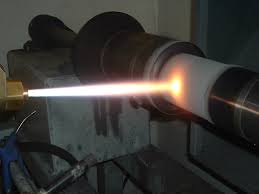
The Taskmaster High Velocity Oxygen Fuel thermal spray process provides High Density coatings with almost Negligible Porosity levels


Quantity : 1 Schematic of HVOF Combustion Chamber
Price : 1
Thermal Spray Process
|
Our company PROCURED WORLD LATEST HVOF SYSTEM FROM TAFA - PRAXAIR Excellence Flame Velocity & Particle Velocity. FLAME TEMPERATURE DURING COATING around 3,000 °C and high bond strength 10,000 psi – HVOF is the latest thermal spray system which is getting wide acceptance worldwide because it finds diverse applications in a cross section of industries.
Coatings applied by our HP/HVOF equipment coatings are characterized by :
· Nearly pore – free density levels
· Low oxide content
· High corrosion resistance
· Good resistance to wear
· Higher bond strength than similar coatings deposited by combustion spry, electric arc spray, or plasma spray processes
Process :
HVOF is a thermal spray system utilizing the combustion of gases, such as Hydrogen or a liquid fuel such as kerosene. Fuel and oxygen mix and atomize within the combustion area under conditions that monitor the correct combustion mode and pressure. The process creates a very high velocity which is used to propel the particles at near supersonic speeds before impact onto the substrate. One of the basic rules of spraying is that high combustion pressure = high gas velocity, high particle velocity and resulting high coating quality. One of the key benefits of this system's high velocity is the extremely high coating density and low oxide content. The low oxides are due partly to the speed of the particles spending less time within the heat source and partly due to the lower flame temperature (around 3,000 °C) of the heat source compared with alternative processes.
Schematic of HVOF Combustion Chamber
Typical HVOF Materials :
· Carbides / Cermets (e.g. WC-Co, WC-CoCr, Cr3C2-NiCr)
· Pure Metals (e.g. Al, Cu)
· Stainless Steel (e.g. SS 304, 316, 410)
· Ni – base super alloy (e.g. Inconel, Hasteally, Selffluxing alloy)
· Co – base super alloy (e.g. Stellites, Triballoy)
· MCrAlY (where M = Ni &/ Co &/ Fe)
· For specials applications: Oxide ceramics like Al2O3 typical grain size of spray powder lies between 16 – 45 µm, also finer powders are used.

Electric arc spraying is a thermal spraying process that uses an electric arc between two consumable electrodes of the surfacing materials as the heat source. A compressed gas atomizes and propels the molten material to the workpiece. The principle of this process is shown by figure. The two consumable electrode wires are fed by a wire feeder to bring them together at an angle of approximatel[..]

Our company PROCURED WORLD LATEST HVOF SYSTEM FROM TAFA - PRAXAIR Excellence Flame Velocity & Particle Velocity. FLAME TEMPERATURE DURING COATING around 3,000 °C and high bond strength 10,000 psi – HVOF is the latest thermal spray system which is getting wide acceptance worldwide because it finds diverse applications in a cross section of industries. Coatings applied by our HP/HVOF [..]

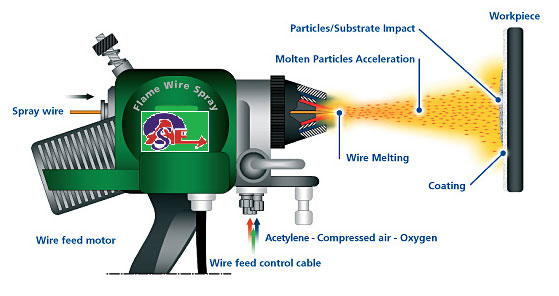
Flame spraying is a thermal spraying process that uses an oxy-fuel gas flame as a source of heat for melting the coating material. Compressed air is usually used for atomizing and propelling the material to the work piece. There are two variations: one uses metal in wire form and the other uses materials in powder form. The method of flame spraying which uses powder is sometimes known as powder fl[..]

The Basics : All thermal spraying processes rely on the same principle of heating a feed stock, (Powder or Wire) and accelerating it to a high velocity and then allowing the particles to strike the substrate. The particles will then deform and freeze onto the substrate. The coating is formed when millions of particles are deposited on top of each other. These particles are bonded by the subst[..]